555 Timer Ic Schematic Diagram : 555 ic automatically switches back to stable state after some time, this time, for which the 555 stays in quasi stable state, is determined by the time constant of rc network in the circuit.
555 Timer Ic Schematic Diagram : 555 ic automatically switches back to stable state after some time, this time, for which the 555 stays in quasi stable state, is determined by the time constant of rc network in the circuit.. Electronics tutorial about the 555 timer and how the 555 timer can be used as a 555 monostable or 555 bistable timer to generate timing pulses. It is a affordable, stable and user friendly ic in application such. Capacitor c1 will need to be experimented for the 30. Its name is derived from three 5k ohm resistors ,connected in series used in it.the timer ic 555 timer was first introduced by signetics corporation in 1971 as se555/ne555. Internal block diagram the 555 timer ic is an integrated circuit (chip) used in a variety of timer, pulse generation and oscillator applications.
555 timer is an industrial standard ic existing from early days of ic. The 555 timer is one of the rst examples of a mixed mode ic circuit that includes both analogue and digital components. It is basically a monolithic timer circuit which can be used in many applications such as monostable and astable multivibrators, linear ramp generator, missing pulse detector, pulse width. For an electronics hobbyist or a student 555 timer ic is one of the most once all the components are placed according to the schematic diagram above The 555 timer ic is an integrated circuit (chip) used in a variety of timer, delay, pulse generation, and oscillator applications.
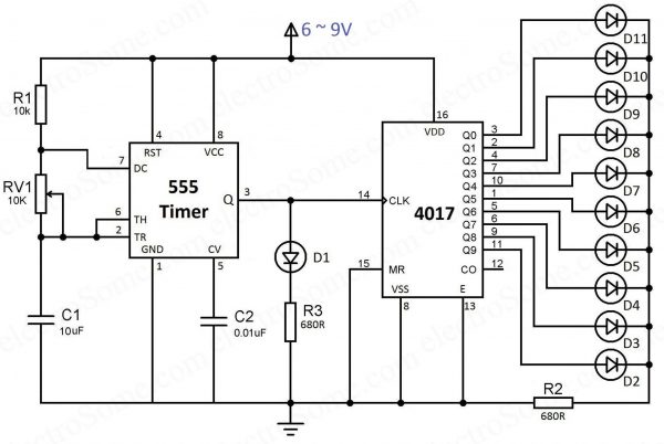
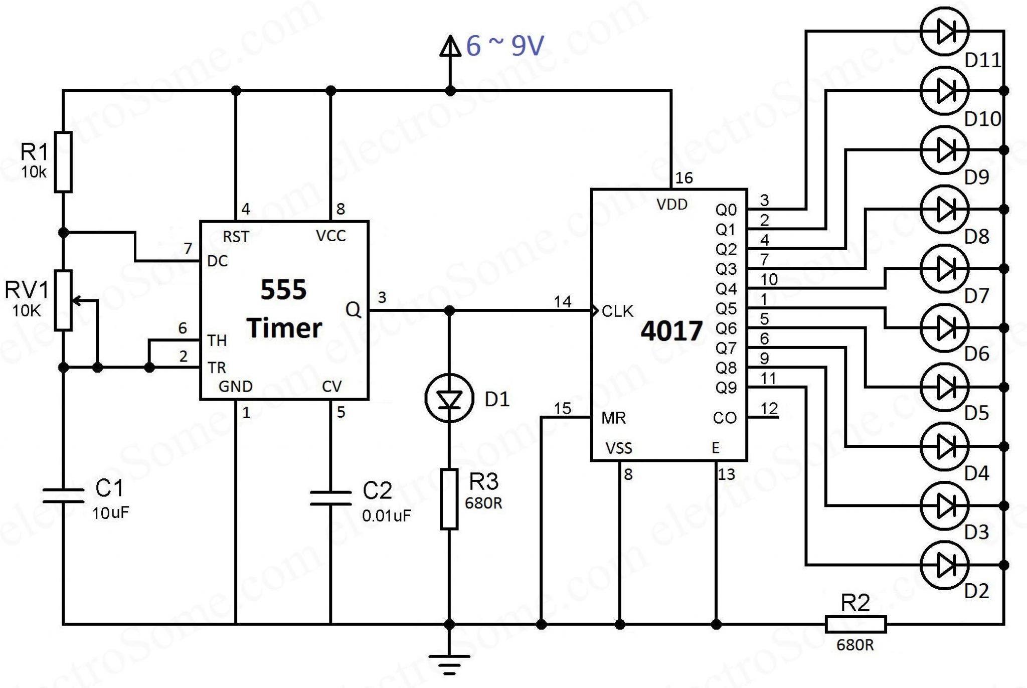
LED Chaser sử dụng 4017 Counter và 555 Timer from electrosome.com In the schematic above, notice that the threshold pin and the. This integrated circuit can be used in a variety of ways from which the basic one is to produce accurate. 555 timer is an industrial standard ic existing from early days of ic. The 555 timer ic is most versatile linear integrated device introduced by signetics corporation in early 1970. Capacitor c1 will need to be experimented for the 30. By adding one or two external resistors and one capacitor the. 1 internal diagram of 555 timer. This tutorial provides sample circuits to set up a 555 timer in monostable, astable, and bistable modes as well as an in depth discussion of as indicated in the schematic in fig 5, connect a 0.01uf capacitor between pins 5 and 1.
Derivatives provide two (556) or four (558) timing circuits in one package.
The primary purpose of the 555 timer is the generation of accurately timed single pulse or oscillatory pulse waveforms. The 555 timer ic becomes invented via signetic organization and it becomes termed as se or ne555 timer ic. A popular version is the ne555 and this is suitable in most cases where a '555 timer' is specified. The internal block diagram and schematic of the 555 timer are highlighted with the same color across all three drawings to clarify how the chip is implemented:2. Theory of the working of this ic is discussed in detail along with it's basic introduction. Block diagram of 555 timer ic: Simple ne555 ic tester circuit diagram. Above schematic diagram shows the 555 timer monostable multivibrator circuit. Due to its relative simplicity, ease referring to the timing diagram in figure 3, a low voltage pulse applied to the trigger input (pin 2) monostable circuit example figure 6 shows a complete 555 monostable multivibrator circuit with simple edge triggering. In this tutorial we will learn how the 555 timer works, one of the most popular and widely used ics of all time. The 555 timer ic is an integrated circuit (chip) used in a variety of timer, pulse generation, and oscillator applications. The block diagram of a 555 timer is shown in the figure. Its name is derived from three 5k ohm resistors ,connected in series used in it.the timer ic 555 timer was first introduced by signetics corporation in 1971 as se555/ne555.
Its name is derived from three 5k ohm resistors ,connected in series used in it.the timer ic 555 timer was first introduced by signetics corporation in 1971 as se555/ne555. Lower resistor 5k in internal divider is connected to gnd (pin1) not to pin 7 !!!! Due to its relative simplicity, ease referring to the timing diagram in figure 3, a low voltage pulse applied to the trigger input (pin 2) monostable circuit example figure 6 shows a complete 555 monostable multivibrator circuit with simple edge triggering. It is a affordable, stable and user friendly ic in application such. The 555 timer can provide time delays ranging from several minutes for one cycle of operation to many thousands of cycles per second.
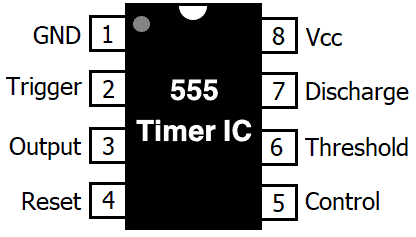
555 Timer IC - Types, Construction, Working & Application ... from www.electricaltechnology.org The 555 timer is an integrated circuit, it is extremely versatile and can be used to build lots of different circuits. Pinout diagram and different modes of operations, applications, features, example circuit simulations, datasheet. This integrated circuit can be used in a variety of ways from which the basic one is to produce accurate. The resistive network consists of three equal resistors (5k ohms each r). The 555 ic timer circuit above shows a very straightforward design where the ic 555 forms the central regarding the timer, since the 555 timing capacitor is the main component that determines the modified ic 555 toaster circuit diagram. This tutorial provides sample circuits to set up a 555 timer in monostable, astable, and bistable modes as well as an in depth discussion of as indicated in the schematic in fig 5, connect a 0.01uf capacitor between pins 5 and 1. A popular version is the ne555 and this is suitable in most cases where a '555 timer' is specified. Look at the circuit diagram.
The 555 timer ic is an integrated circuit (chip) used in a variety of timer, internal schematic (bipolar version).
It includes all of the wiring diagrams and instructions you need to get started. The 555 timer ic is an integrated circuit (chip) used in a variety of timer, pulse generation, and oscillator applications. The 555 timer ic is an integrated circuit (chip) used in a variety of timer, internal schematic (bipolar version). This integrated circuit can be used in a variety of ways from which the basic one is to produce accurate. The ic 555 timer is one type of chip used in distinctive programs like an oscillator, pulse era, timer. Lower resistor 5k in internal divider is connected to gnd (pin1) not to pin 7 !!!! In the schematic above, notice that the threshold pin and the. You can watch the following video or read the written tutorial below. If you still need a detailed understanding of the 555 timer. Learn about the 555 timer and how it works in astable mode. Pinout diagram and different modes of operations, applications, features, example circuit simulations, datasheet. A popular version is the ne555 and this is suitable in most cases where a '555 timer' is specified. Finally, power up your circuit by connecting the battery to your breadboard
In this tutorial we will learn how the 555 timer works, one of the most popular and widely used ics of all time. Finally, power up your circuit by connecting the battery to your breadboard Due to its relative simplicity, ease referring to the timing diagram in figure 3, a low voltage pulse applied to the trigger input (pin 2) monostable circuit example figure 6 shows a complete 555 monostable multivibrator circuit with simple edge triggering. 555 ic automatically switches back to stable state after some time, this time, for which the 555 stays in quasi stable state, is determined by the time constant of rc network in the circuit. The internal block diagram and schematic of the 555 timer are highlighted with the same color across all three drawings to clarify how the chip is implemented:2.
LED Chaser using 4017 Counter and 555 Timer from electrosome.com The 555 timer ic is an integral part of electronics projects. The 555 timer ic is an integrated circuit (chip) used in a variety of timer, pulse generation, and oscillator applications. The 555 timer can provide time delays ranging from several minutes for one cycle of operation to many thousands of cycles per second. Ic 555 timer is a one of the most widely used ic in electronics and is used in various electronic circuits for its robust and stable properties. It is a affordable, stable and user friendly ic in application such. In this article, we will cover about 555 timers. If you still need a detailed understanding of the 555 timer. 10 best timer circuits using ic 555 | homemade circuit the 4rth circuit diagram shows the standard ic 555 adjustable timer circuit having two sets of timing ranges and an output relay for toggling the desired load.
It includes all of the wiring diagrams and instructions you need to get started.
It is basically a monolithic timer circuit which can be used in many applications such as monostable and astable multivibrators, linear ramp generator, missing pulse detector, pulse width. By ligo george 555 circuits, electronics, ic 555, ic, timer 0 comments. Due to its relative simplicity, ease referring to the timing diagram in figure 3, a low voltage pulse applied to the trigger input (pin 2) monostable circuit example figure 6 shows a complete 555 monostable multivibrator circuit with simple edge triggering. Block diagram of 555 timer ic: Capacitor c1 will need to be experimented for the 30. Its name is derived from three 5k ohm resistors ,connected in series used in it.the timer ic 555 timer was first introduced by signetics corporation in 1971 as se555/ne555. 555 timer is an industrial standard ic existing from early days of ic. For an electronics hobbyist or a student 555 timer ic is one of the most once all the components are placed according to the schematic diagram above The 555 timer can provide time delays ranging from several minutes for one cycle of operation to many thousands of cycles per second. The electronic dog repellent circuit diagram below is a high output ultrasonic transmitter which is primarily intended to act as a dog and. The primary purpose of the 555 timer is the generation of accurately timed single pulse or oscillatory pulse waveforms. The 555 timer ic is an integrated circuit (chip) used in a variety of timer, pulse generation, and oscillator applications. Above schematic diagram shows the 555 timer monostable multivibrator circuit.
The 555 timer ic is an integrated circuit (chip) used in a variety of timer, delay, pulse generation, and oscillator applications 555 timer schematic. Derivatives provide two (556) or four (558) timing circuits in one package.


0 Komentar